.png)
|
|
||||||
|
"High Efficiency and high power density Internal Combustion Engine" Advantages of AB Engine compared to conventional Otto, Diesel, Miller or Atkinson engines
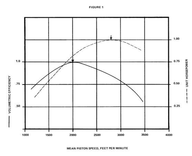
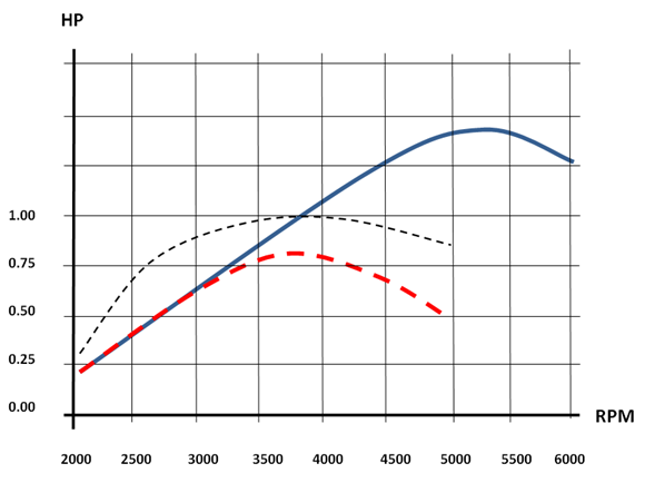
Summary In this article we are explaining how AB engine cycle works compared to the conventional (Otto, Atkinson and Miller) engine cycles. The fuel efficiency of the AB engine is the same as in Atkinson, while avoiding its well-known disadvantages such as poor power density and complicated mechanical design that provides for a different piston stroke during intake and exhaust parts of a cycle. In AB engine one can achieve equally-impressive high power density and fuel efficiency without design complications. As an example, we are taking a typical Pontiac engine performance data and comparing it to simulated performance of the AB and Atkinson engines. Specifically, we simulated the modification of the Pontiac to the AB engine by keeping the same combustion volume while increasing compression/expansion ratio by a factor of two and implementing secondary AB engine intake “time variable valve” controlled by a computer. Figure 1 depicts power output in relative horsepower (HP) units vs. revolves per minute (RPM), where the maximum power output of Pontiac engine is taken to be equal to 1.0 Specific advantages detailed in this paper are as follows:
AB engine cycle can be implemented in any adiabatic internal combustion engine including Diesel and Miller engines, and it can work with any type of fuel increasing both engine efficiency and power density.
Figure 1 shows the comparison of the AB engine and Atkinson power output curves to a typical Pontiac engine power output curve
1. Fuel efficiency Advantage When used in almost any adiabatic internal combustion engine (ICE), the proposed AB engine cycle will yield the same fuel efficiency advantages as the well-known Atkinson engine cycle [1], but with a significantly simpler mechanical design that enables a number of advantages.
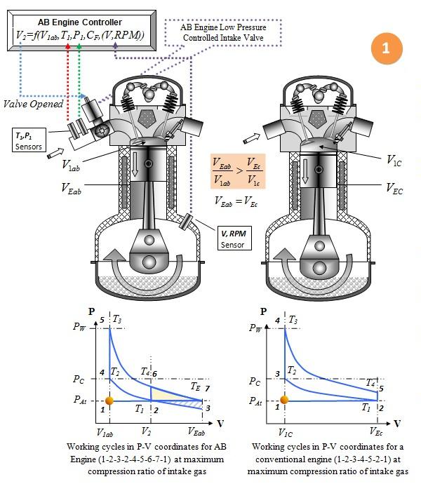
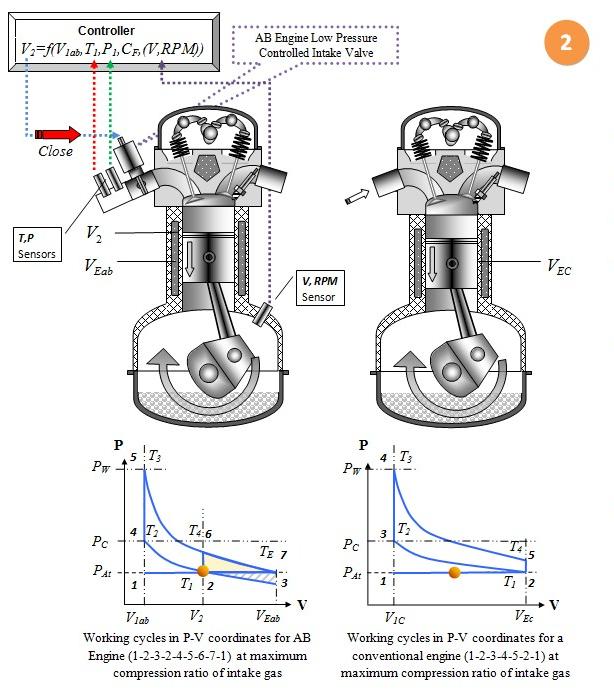
Figure 2 (a) AB engine; (b) Atkinson engine The above figure depicts AB engine (a) and Atkinson engine (b) cycles. In both cycles we show equivalent Otto (Diesel) cycle within the larger cycles, which is depicted by the blue area in Atkinson diagram, and as region 2-4-5-6 in AB engine diagram. In AB engine cycle we show equivalent Atkinson cycle as 1-2-4-5-6-7-1. Additional energy produced by burning the same amount of fuel is shown as the red areas in the Atkinson diagram and as the green region 2-6-7 in the AB engine diagram. Even though calculations of fuel efficiency [2] are the same, the cycle and practical ways of achieving each cycle are different. Atkinson cycle uses complicated mechanical approach to create the necessary compression ratio depending on the fuel, while avoiding detonation, and creating increased expansion ratio in order to gain higher efficiency compared to Otto or Diesel cycles. In contrast, AB engine uses a thermodynamic approach that utilizes certain adiabatic parts of the engine cycle in order to achieve the same goal as in the Atkinson cycle without design complications. In fact, it uses almost the same simple engine configuration as Otto, Miller or Diesel engines. All advantages of the AB engine cycle stem from high compression/expansion ratio and from the application of a specific control of the air flow using secondary intake valve. This results in an optimal actual compression ratio for particular fuel and utilization of high expansion ratio for increasing the fuel efficiency. As we can see from Figure 2 (a), the difference in Atkinson cycle is the adiabatic expansion-compression part of the diagram depicted by 2-3-2. This part of a cycle doesn’t consume or produce any energy but plays a significant role in AB engine operations. More details on the differences of AB engine design compared to conventional and Atkinson engines can be found on our web page, in [3] as well as in this document. Efficiency of the AB engine cycle (as well as that of Atkinson’s ) is the highest theoretically possible for adiabatic ICE, mainly because of the possibility of expanding burnt gases up to the point where the exhaust is at ambient environmental pressure.2. AB Engine secondary intake valve advantages One of the primary features of AB engine is a secondary intake valve that works differently from traditional engine valves. AB engine’s secondary valve performs under intake air pressure and temperature. This implies atmospheric pressure or below (for high altitudes). It may be also higher than atmospheric if used after a “turbocharger”, such as in Miller type engines. In any case, this pressure environment in which the valve operates is moderate; the AB engine secondary valve is not exposed to high temperatures and pressures as conventional intake valves implemented as a part of a combustion chamber. AB engine secondary valve can be easily manipulated by any kind of a drive, including electromagnetic, and can be designed with minimum air resistance. The valve only needs to be closed at specific piston positions and to be opened at any time by the controller after the intake cycle is completed. Low working pressure and temperature open up a way of using this secondary valve as a simple time variable valve that can be controlled by a computer with algorithms that optimize engine performance. One of the advantages of using AB engine secondary intake valve is in avoiding power output control by throttle. Manipulating power output by secondary valve, closing it at specific piston position restricting amount of intake air will put full intake cycle in adiabatic stage and avoid pumping losses caused by the throttle resistance.3. AB Engine intake air flow resistance compensation advantages Low volumetric efficiency (VE) is a well know problem for engines. AB engine intake air flow resistance compensation works keeping VE at 100% or even exceeding it (if needed) for the most of engine RPM range. First we should explain what engine volumetric efficiency parameter means. Volumetric efficiency in the internal combustion engine design is a ratio (or percentage) of the amount of air (oxidizing media) that is trapped by the cylinder during intake cycle, to the volume swept in the cylinder under static conditions. Usually, after reaching maximum value, VE decreases with increasing of RPM due to the air flow resistance caused by: ● air filter resistance ● throttle damper resistance ● aerodynamic resistance of manifolds ● intake valve resistance Volumetric efficiency is one of the most important engine parameters that are difficult to maintain at high levels in conventional Otto or Diesel engines. Below (Fig.3) is the typical VE/RPM diagram depicting two most important curves, the VE and engine torque as a function of the engine’s single cycle power output. As seen in Fig.3 below, the VE changes with RPM in a way similar to the torque, with some difference occurring at high RPM, where conditions for fuel burning are different from the ones at low RPM [4].
Figure 3 shows original chart [4] of illustration of fundamental relationship between peak torque and peak volumetric efficiency (VE) with engine RPM In Otto and Atkinson engines, the VE peaks and then drops, due to the air flow resistance created by reasons mentioned above. Note that the decrease in horsepower with RPM is about 90% due to the declining VE, which is clearly seen in Figure 3 (please read a NOTE below the chart). This means that if we could keep the VE close to 100%, then the engine power output curve would continue to rise almost linearly with RPM. This would significantly increase the engine performance. One possible realization of this would be to use a turbocharger to increase air pressure and compensate for air flow resistance. The addition of a turbocharger to the Otto engine represents the Miller cycle engine. However, increasing engine power density in Miller engines does not increase the fuel efficiency from fundamental (thermodynamic) point of view because of the same low expansion ratio of burnt gases. On the contrary, the AB cycle does increase engine efficiency as well as its power density. Because of specific feature of the AB engine during intake cycle (2-3-2 Fig.1), where air trapped in combustion chamber has lower pressure than initial intake pressure, there is a possibility of “compensating for air flow resistance,” using AB engine secondary valve as a time variable valve. That represents a significant difference from Otto, Atkinson and Miller engine cycles. AB engine air flow compensation ability keeps the AB engine VE close to 100% for most reasonable engine RPM values without using a turbocharger. At the same time, AB cycle will improve Miller cycle as well, increasing its performance in terms of fuel efficiency and power density. We would like to point out that VE for an Atkinson engine with similar expansion volume as in the Pontiac engine will be the same as in Otto engine. This similarity is a cause of poor power density in an Atkinson engine, even though there are fuel efficiency advantages. Mechanical complications and poor power density makes Atkinson engine unattractive for many applications. An example showing a modification of a conventional Otto engine into an AB engine configuration
Figure 4 Curves of VE and relative HP for a very typical Pontiac engine. The curves shown in this figure are taken from Ref. [5]; here RPM = FPM×1.42 Using this Pontiac engine performance chart as an example; we will try to show how the engine will perform if we modify it to the AB engine configuration while keeping the same engine volume. We can clearly see that after the VE value reaches its peak at 2000 FPM (about 2800 RPM) , the horsepower of the Pontiac engine starts declining together with VE. At about of 2800 FPM (about 4000 RPM) it reaches the maximum. Possible modification of Pontiac engine into the AB engine is represented below, with conventional Otto engine shown on the right and the modified one on the left.
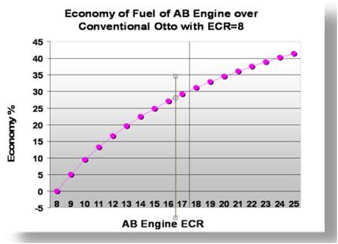
Figure 5 (Full description is at [3] slide 1) shows Otto (similar to Pontiac) engine on the right and AB engine on the left. The modification includes: 1. Increasing compression ratio by a factor of two (as an example), from the usual value of 8 to 16, which will increase efficiency by about 28% (see figure 6 below)
2. Implementing AB engine secondary intake valve. 3. Implementing sensors for monitoring piston position, RPM, intake air pressure and intake air temperature. 4. Implementing a computer that takes all these measured parameters and calculates the right moment for closing the AB engine valve, to keep the compression ratio (and thus VE) at an optimum value.
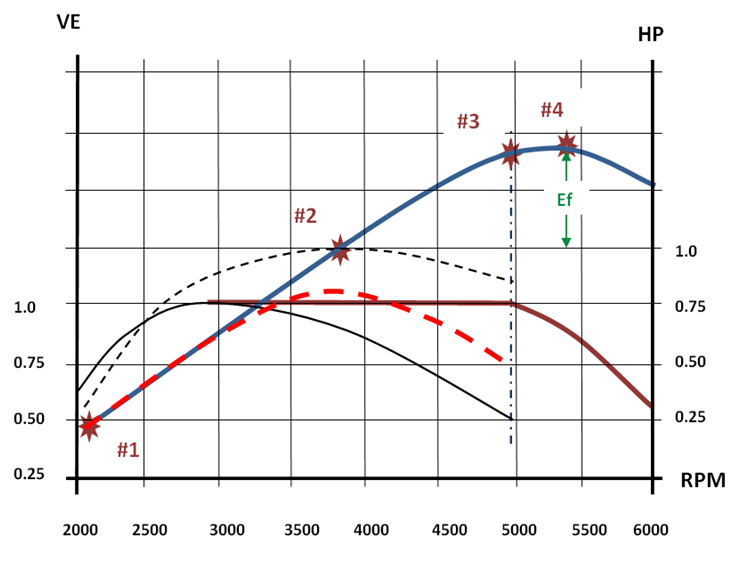
Figure 7 shows the result of the implementation of the AB engine cycle modifying Pontiac engine. In order to reach the optimum compression ratio (such as ECR = 8 or other, depending on the fuel used), for example having ECR = 16, we need to close the AB engine secondary valve at a volume V2 (see Fig. 8) that corresponds to the amount of intake air necessary to create actual compression ratio 8.
Figure 8 (Full description is at [3] slide 2) shows Otto (similar to Pontiac) engine on the right and AB engine on the left at a point where AB engine secondary valve is closed at V2. For each particular engine configuration a map will be created (or calculated in real time of the closing position of intake time variable valve above or below V2 (Fig. 8) versus RPM, and intake air temperature and pressure. Every intake air flow compensation action will determine the closing position above or below V2 (Fig. 8) a. Compensation of intake air flow resistance due to increased RPM
For each RPM value, engine computer will calculate the best adjustment VADJ for closing of AB valve at volume V2 + VADJ. This can be explained with the Fig. 7 diagram showing how Pontiac engine is expected to perform after being modified into AB engine configuration.
Bellow is an explanation of the VE and power output curves of Fig 7:
· First let us define the VE for AB engine cycle: it is the efficiency of reaching the optimal volume (or gas mass) of intake air at the initial (static) V2 position (Fig.8), at the atmospheric pressure. This volume, if compressed, will create VE close to 100%. This will result in maximum possible compression ratio for the particular fuel used for performance without detonation. · The VE curve before it picks will be almost the same for all types of engines in case of using a throttle to control engine power output. The more important parameter is the corresponding power output curve compared to unmodified engine after reaching maximum VE · As a starting point Fig. 7 point #1, it may be assumed that there is a 50% drop in AB engine(and Atkinson) power output of a cycle due to a ECR change from 8 to 16, due to half the air needed. In fact this is not true. Due to increased efficiency (~28% in our example, see Fig. 6) the single cycle power output (torque) will drop only about 35% - instead of 50% in this case. · For AB Engine, at increased RPM, the computer will close the AB engine secondary valve later according to calculated VADJ to maintain the actual compression ratio constant at a VE value of 100%. Consequently, this will also keep the torque almost constant, thus increasing AB engine power output almost linearly with RPM up to the point #3 (Fig. 7). At this point the Pontiac engine VE is only 0.5 that is a maximum for AB engine air volume at VE=100% (for this particular modification). After Point #3, the AB engine secondary valve will be always open and AB engine VE curve will be going down the same way as in a Pontiac (Otto) engine. · We can see that even though single engine cycle power output (torque) of AB engine is less than in unmodified Pontiac engine at the beginning, it becomes higher starting from Point #2 (Fig. 7) at about ~3700 RPM) This happens because the torque in Pontiac engine starts declining from ~ 2850 RPM, but torque of the AB engine continues to climb linearly until both engines power output become equal at ~3800 RPM This is a very important point that shows significant advantage of AB engine compared to Otto and Atkinson engines. At Point #2 the modified Pontiac engine will perform with the same power output as unmodified but with 28% higher efficiency than in the conventional Otto configuration! · Finally at point #4 the AB engine will reach its maximum power output at about ~5400 RPM. The idea behind the increased maximum of the AB engine power output is rather simple. We expect AB engine maximum power output will increase by the same value as the engine efficiency. In this particular example it is about 28%.
At Point #4 the modified Pontiac engine will perform with 28% higher power output and fuel efficiency compared to the conventional configuration! Power output will be increasing up to 5400 RPM that is almost the maximum RPM for that particular engine. Conclusion: Implementation of AB engine cycle and air flow resistance compensation will not only improve the engine fuel efficiency significantly, but will also increase the engine performance (power output) starting from the moderate RPM, in our case ~3400 RPM. b. Compensation for change of intake air pressure and temperature. It is known that the intake air temperature and pressure will change the required actual compression ratio to ensure engine operation without knocking (air-fuel mixture detonation). AB engine configuration will allow this kind of compensation in a wide range of pressures and temperatures such as: - At high altitudes where pressure is low and temperature is low as well - In summer or winter seasons - In northern (Arctic) or southern (Antarctic) regions or very “hot” regions – deserts. - In Miller engines after turbocharger. The advantage of using the compensation at decreased temperatures is only available in an AB engine configuration and is not possible in Otto or Atkinson configurations. Compensation will allow AB engine to produce higher power output in winter times or if engines are used in Arctic and Antarctic regions [did you not just said that already? Do not repeat]. In regions with very high temperature such as in Sahara desert, the compensation will prevent engine knocking. Regardless of temperature and pressure, it will always adjust V2 position (Fig. 8) to keep engine performance and fuel efficiency at the optimum level. c. AB engine intake valve in multi-piston engines. AB engine’s secondary intake valve also has an advantage of providing the intake air flow compensation in multi-piston engines at low power output. Some of the pistons can be disengaged by closing the valve completely or partially, leaving fewer pistons working in certain conditions for optimal performance. References: 1. http://energyclimatetransportation.blogspot.com/2013/10/a-tale-of-two-cars.html 2. http://abengine.com/fuel-efficiency.htm 3. http://www.abengine.com/technology_presentation.htm 5. http://www.wallaceracing.com/enginetheory.htm
Visits since June 2, 2016:
|
|
|||||
|
|
||||||
.png)