|
Technology Presentation |
|||||
|
|
Exhaust Stage
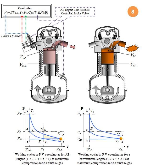
· The exhaust valves are opened at both engines. Excessive pressure in the conventional engine bursts out with an explosion, wasting the fuel energy that the AB Engine would utilize towards work in its place. The P-V diagram shows this in a conventional engine as a pressure drop from point 5 to 2. AB Engine can have no pressure difference or smaller pressure, but not more than between point 6 and 7 if the engine is to be designed with a smaller expansion ratio. AB Engine exhaust pressure can be even less than atmospheric pressure if it designed to use different kind of Octane ratio gasoline fuels. The compression ratio of AB Engine will be optimized for higher Octane ratio fuel in this case. If a smaller Octane ratio is to be used in such an engine, the exhaust gas pressures will be below atmospheric, still performing with maximum theoretical fuel efficiency. · The possibility of designing the AB Engine with less exhaust gas pressure simplifies exhaust collector design which would have to operate at high pressure and temperature otherwise (as in a conventional engine) · The smaller exhaust gas temperature allows for a less extensive cooling system · It is important to notice that the AB Engine P-V diagram consist of two major parts. Area 2-4-5-6-7-2 describes the energy created by the AB Engine from one unit of gas-fuel mixture. We have already mentioned that all the P-V features describing area 2-4-5-6-2 are similar to 2-3-4-5-2 in the conventional engine diagram. This means that area 2-4-5-6-2 in the AB Engine P-V diagram represent the thermodynamics of a conventional engine that has a similar volume (V1) to that of the AB Engine. The additional area on the AB Engine P-V diagram 6-7-2 represent the extra work that the AB Engine produces compared to a conventional engine from the same amount of fuel. Next slide will explain and compare the fuel efficiency of an AB Engine to a conventional one.
|
||||
|
|
|||||
|
|
|||||
